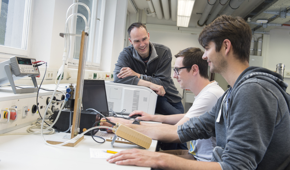
Laboratory exercises and projects - General metrology
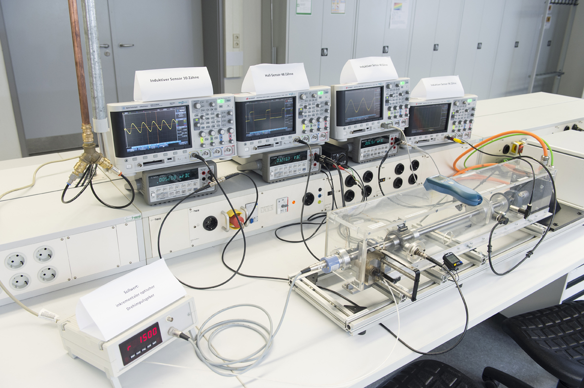
Rotational speed measurement
Several methods to measure the rotational speed of the shaft are lined up on a shaft driven by a brushless DC motor. The signals output by the sensors are visualised with digital storage oscilloscopes and a frequency counter. The measurement errors of the measurement methods are determined and compared. The ability to measure at low speed or at large distances from the shaft is investigated as well.
Pressure measurement
The use of various pressure sensors such as piston manometer and pressure balance, liquid U-tube manometer, bellow manometer through to integrated micromechanical membrane sensors to measure absolute and differential pressures in gases and liquids is demonstrated. The sensors must be calibrated with the aid of calibration equipment and their characteristic curves recorded. Terms such as linearity, error classes and hysteresis errors are an essential part of this experiment.
Flow measurement
The exercise involves measuring the flow velocity and the mass flow in a fan. The sensors used are turbine flow meters, rotary-vane and hot-film anemometers, differential pressure sensors in combination with standard orifices or pipe bends and the Prandtl (Pitot-static) tube. Pressure, density and temperature must be taken into account.
Temperature measurement
This experiment uses PTC and NTC thermistors, platinum resistance thermometers, thermocouples with compensation, and conventional as well as computer-aided evaluation. Particular emphasis here is placed on transient behaviour at the sensor, in the processing of the measurement data and at display and registration devices. Measures to allow the faster determination of temperature are explored.
Strain gauge metrology
As part of this experiment, each team of students produces a balance with a measuring range of 0 to 30 kg. All individual steps needed for the application of strain gauges on a cantilever beam, for the zero balancing, and the amplifier calibration of the conventional or computer-aided evaluation electronics must be carried out by the students themselves. In conclusion, the linearity and hysteresis of the balance is reviewed.
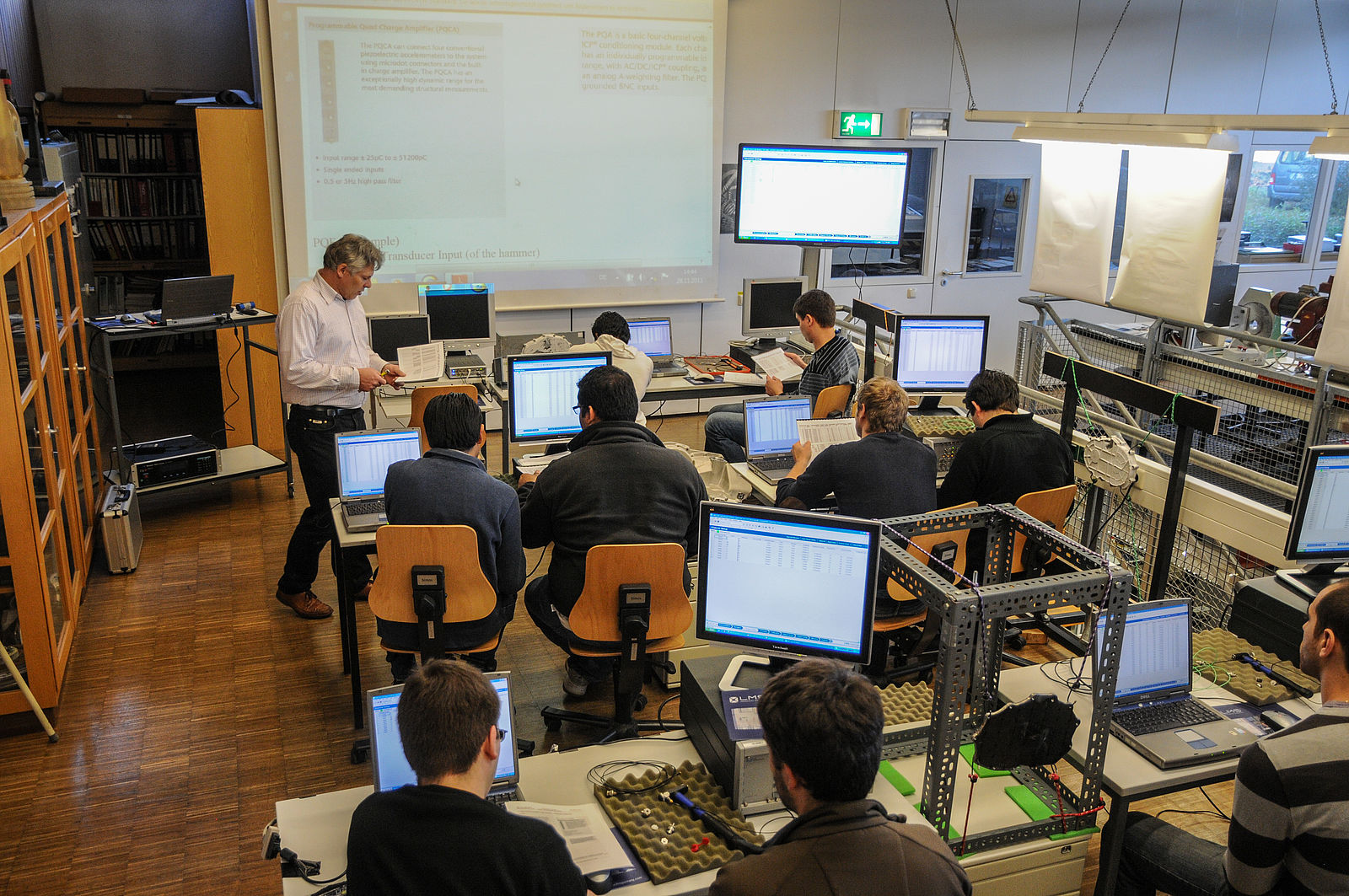
Use of measuring data acquisition systems
In this exercise, students familiarise themselves with computer-aided metrology with measurement systems. The students store the data for the sensors in the system. In doing so they take into account the criteria for setting the sampling rate, and the setting of low-pass and high-pass filters. The data collected are processed with the evaluation interface and displayed in graphic form.
CAN sensors
This is a project whereby students investigate CAN databus-capable sensors with the aid of software, read out the data and visualise them. The basics of bus systems in the vehicle and the structure of CAN messages are explored by the students themselves.
Further projects:
The students take on projects to work out solutions to metrological problems such as the sealing of cable penetrations against a low pressure in the vicinity of the sensor.
Further topics are the planning of new laboratory experiments and visualisation aids for lecture content such as the representation of a transient of current and voltage in an RC element.
Laboratory exercises and projects - Laser metrology
The experiments are performed by groups of students (2-5 people).
Fundamentals of optics: diffraction, interference
Interferometers, for example, are set up on vibration-isolated tables using lasers and optical components.
Holography / speckle interferometry
- Setup to produce a double-exposure hologram
- Evaluation of interference lines with an image processing system
- Deformation measurement on a pressure vessel
- Determination of the resonance frequencies on a gearbox cover
- Determination of the operating deflection shapes (ODS) at different frequencies.
Moiré method/ speckle shearing interferometry/ Gray code method
- Deformation measurement on a plastic vessel under internal pressure
- Testing of a carbon-fibre component for delaminations
- Digitisation of a component and export of STL files.
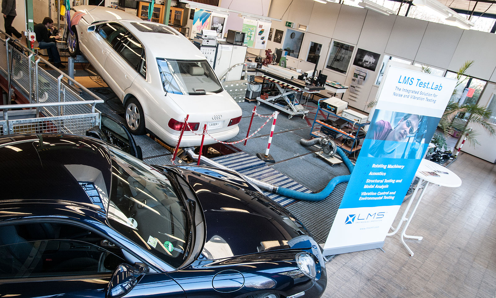
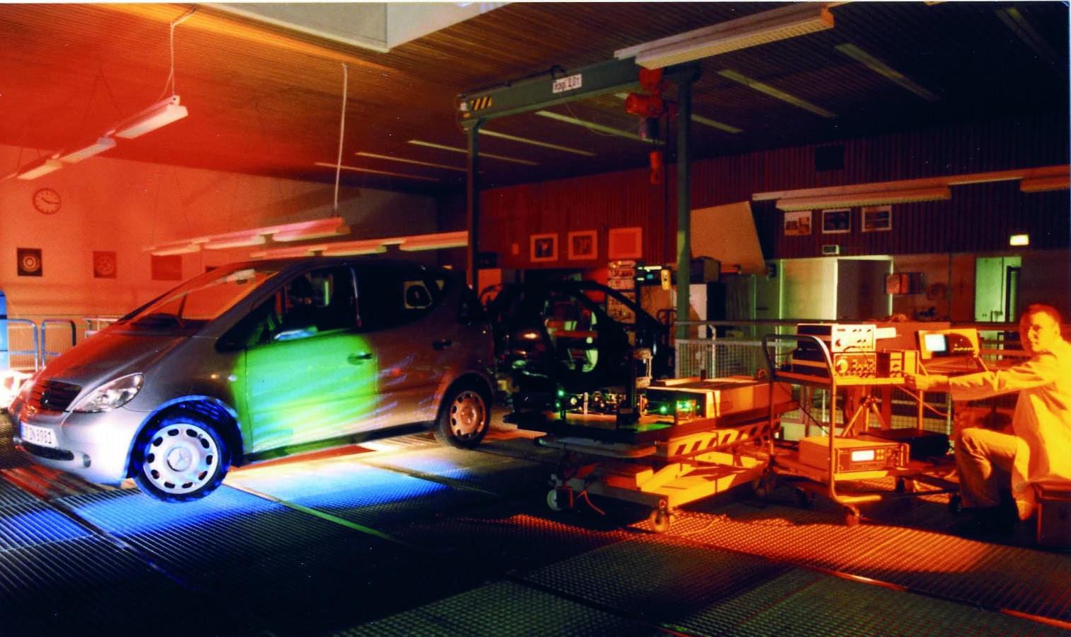
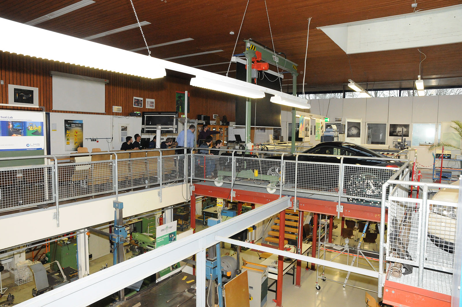
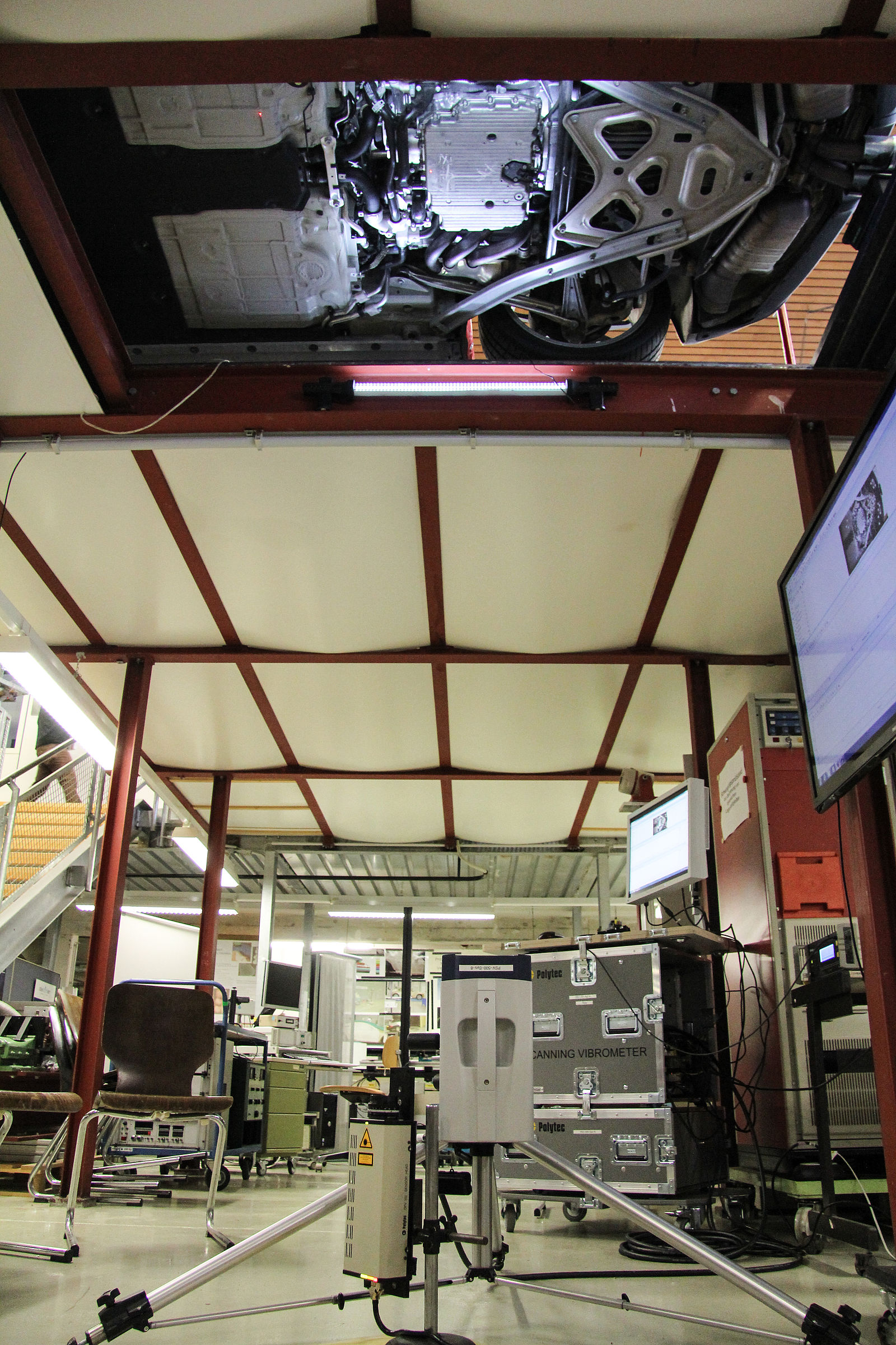
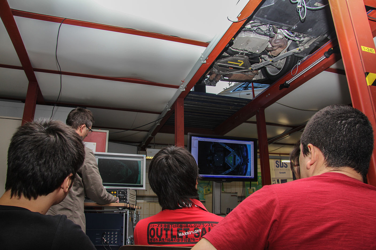
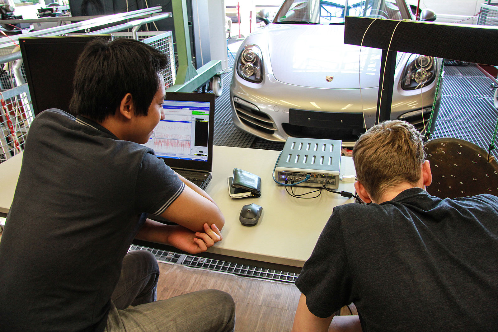
Vibration measurement on the laboratory vehicle with the laser scanning vibrometer
With the engine running, operating deflection shapes are measured on the vehicle underbody and the exhaust system.
Sensors/excitation of vibration
Various sensors (acceleration sensors, microphones, ...) are calibrated, various types of vibration excitation with electrodynamic shakers are compared (sinusoidal, periodic chirp, noise,...).
Resonances and operating deflection shapes
An impact hammer and acceleration sensors are used to determine the resonance frequencies and associated operating deflection shapes on a gearbox cover.
Order analysis
As the engine of the laboratory vehicle is being revved up, deflection shapes and resonance frequencies are determined on the vehicle underbody (waterfall charts) by means of a multi-channel acceleration measurement.
Sound intensity measurement
For a loudspeaker system, a sound intensity probe is used to determine the frequencies emitted at the different loudspeakers.
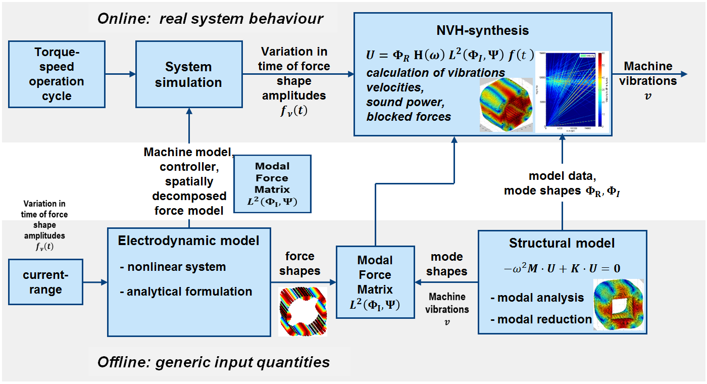
Modal analysis and simulation
The modal deflection shapes on a component are determined by simulation and the measurement data are compared with the results of the modal analysis.