Vehicle concept for needs-based local public transport
The idea of a needs-based local public transport system is not new – the first known system started at the end of the 1970s. Economic reasons have meant that these systems have so far not been able to assert themselves very successfully. The needs-based and user-oriented local public transport system has to have small and manoeuvrable vehicles for narrow, congested residential areas, which transport relatively small numbers of people at the same time. Driver-based operating models incur high staffing costs here.
Essential aspects such as barrier-free boarding and alighting or the interior dimension concept were taken into account as part of the complex vehicle development process.
Whole vehicle

Modern, user-centred vehicle development is based on the systematic requirements definition. In the case presented, the essential main requirements presented below were formulated:
at least 6 seats and further room for standing, low-floor option and completely disabled friendly, autonomous driving mode, fully electric drive, two axles, 50 km/h operating speed, 80 km/h maximum speed.
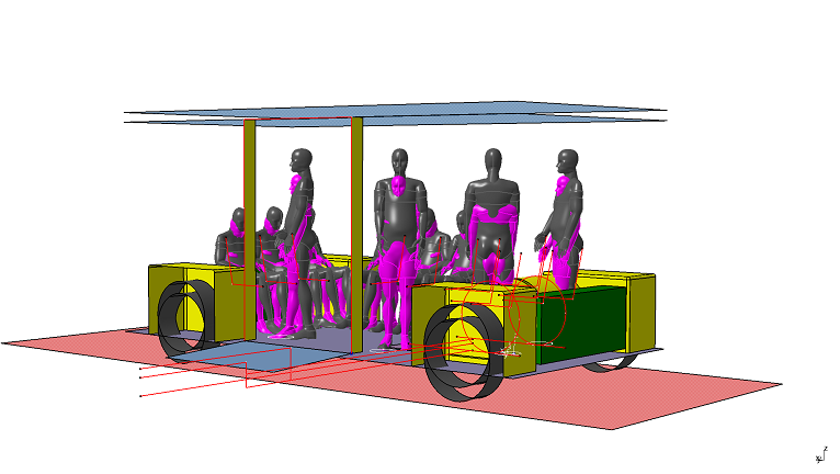
The interior design and the resulting vehicle length, width and height among other things were developed using a centrifugal design strategy which put the user at the centre. It used the RAMSISTM digital man model to take the physical needs of the bus users as its basis. From observations of the current utilisation behaviour, four different utilisation scenarios were derived, which resulted from the vehicle use at different times. Different types of users used the vehicle’s interior space in different ways, from which the following four utilisation scenarios were drawn up for the virtual interior space design:
morning rush hour: full occupancy with ten commuters (sitting and standing room filled to maximum capacity)
during the morning: a parent with a pram, two people with restricted mobility with walking frames and two people with luggage (maximum capacity of the multifunctional area); afternoon: two people with walking frames, one person with a wheelchair, two commuters (design w.r.t. disabled-friendliness); late evening: three persons from/to evening event, one commuter (design w.r.t. space functionality and spatial feel).
The utilisation scenarios were checked with passenger and luggage counts when the needs-oriented bus system was actually in operation (Fig. 2).
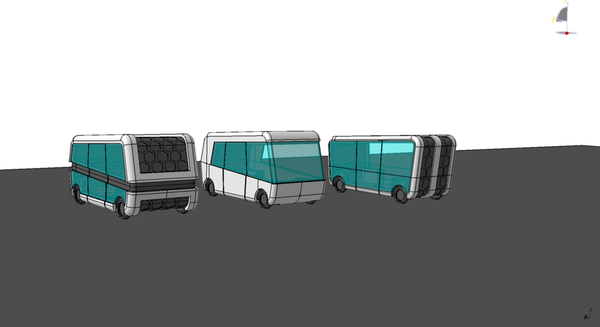
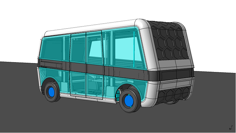
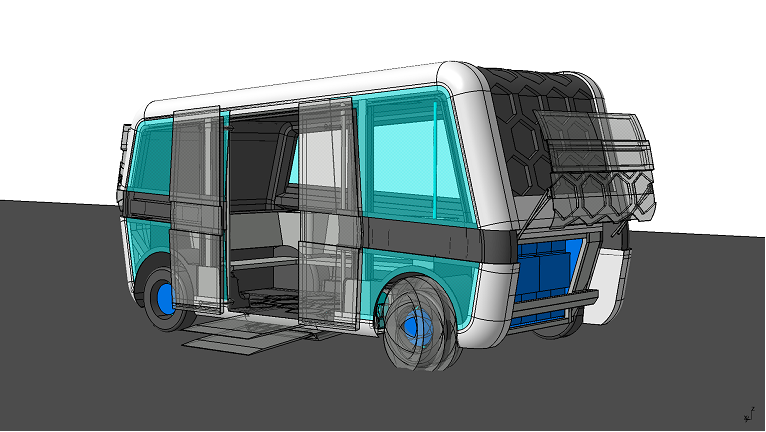
The vehicle concept involved the compilation of various design variants based on the constructed size specifications of the dimension concept (Fig. 3).
Bodywork
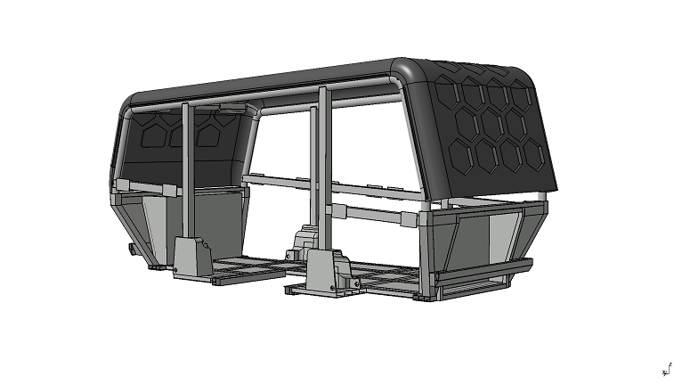
The bodywork development was based on the results of the ergonomic studies and put the focus on being disabled-friendly and the requirements of the packaging, which result from the essential technical components such as drive, chassis and suspension. It had to integrate the design specifications as well, however. The Faculty of Automotive Engineering then took this as the basis for drawing up initial, rough concepts. To enable the bodywork to be designed so as to be commensurate with the loads, the Institute of Vehicle Concepts at our project partner, the DLR, used topology optimisation to calculate bodywork concepts and also performed FEM simulations (Figure 4).
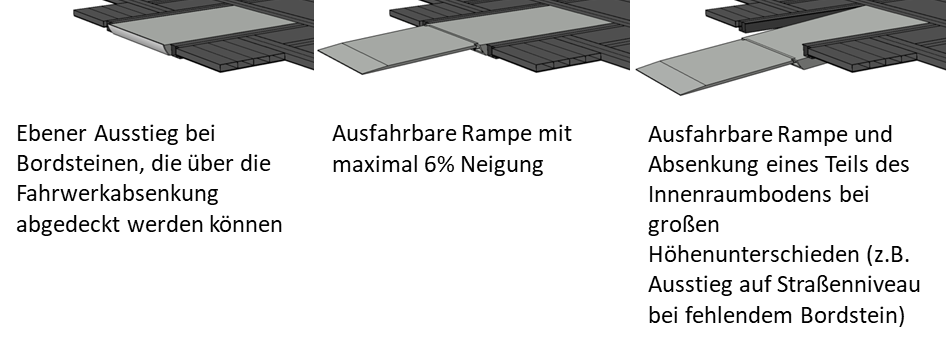
For the boarding and alighting concept, on-site analyses of the existing infrastructure were carried out, as were laboratory analyses, especially in respect of the disabled-friendliness of the vehicle concept. The disabled-friendliness was realised via a height-adjustable chassis and an extendable ramp, which lowers a part of the interior floor as well when large height differences need to be overcome, such as alighting to the road level (Fig. 5).
Drive/suspension
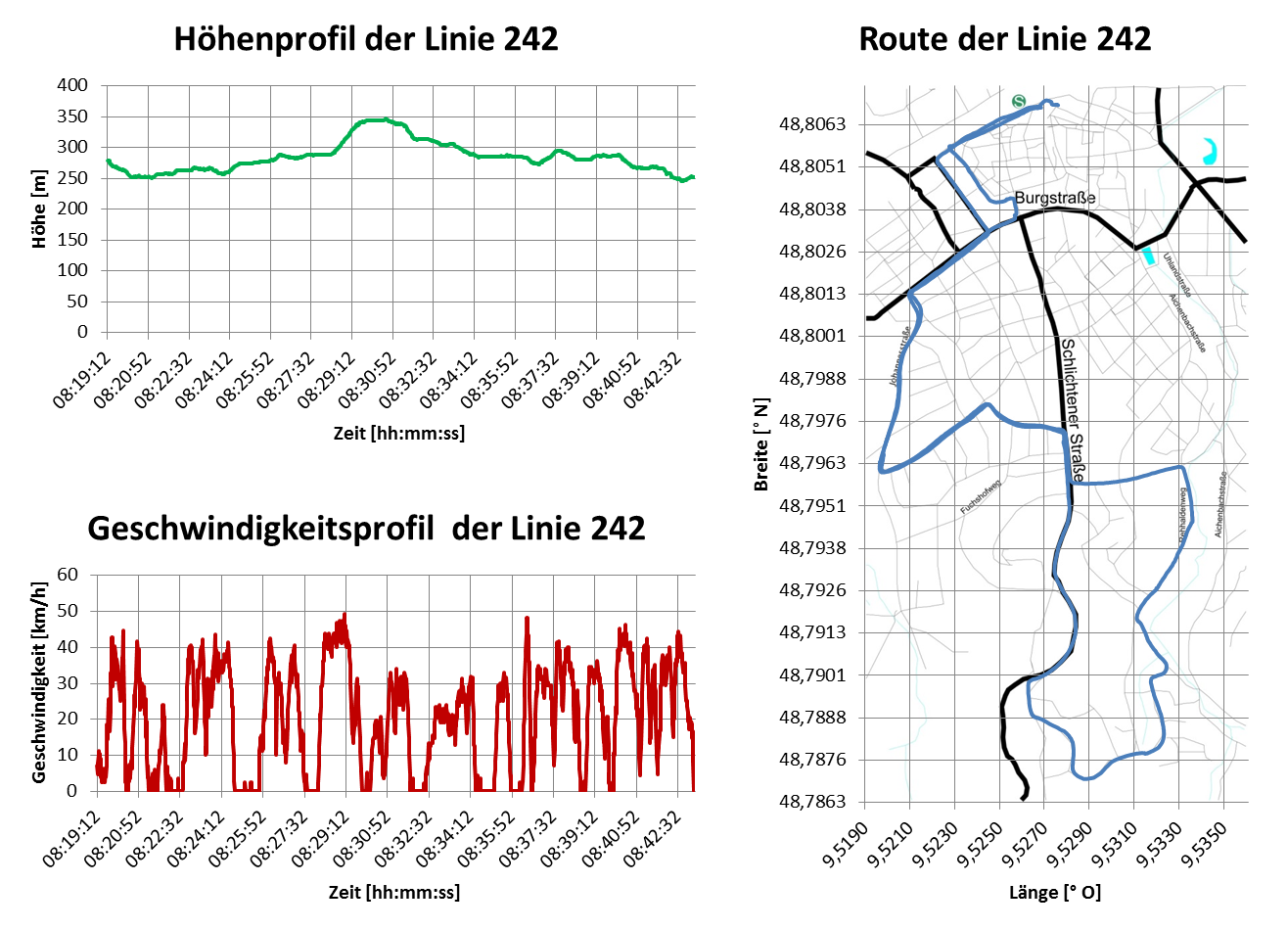
In the inner city, noise emissions are to be greatly reduced and air pollution prevented by means of a purely electric powertrain. A rough design of this powertrain was produced on the basis of the routes travelled by the inner-city buses. The route parameters recorded were then taken as the basis of an analytical consumption estimation conducted with Matlab. From the results, appropriate electric wheel hub motors could be selected by considering the energy needed to travel the maximum speed on the level on the one hand, and to set the bus in motion on a hill with the largest assumed incline while carrying a full payload on the other. If we additionally take into account the travelling time of at least three hours which has to be managed with one battery charge, we obtain the number, size and weight of the battery modules necessary for the drive. Additional energy storage capacity was provided for the air-conditioning of the passenger compartment. For dimensional reasons, longitudinal control arms were chosen for the chassis and equipped with active spring damping systems for passenger comfort. One special feature of the vehicle is its ability to lower its chassis over a very large range.
Fig. 6 Altitude profile, velocity profile and travel route recorded for the No. 242 bus.
Outcome
A result which combines the sub-concepts described into a balanced overall concept was derived systematically.
At the conclusion of the project, the results of the vehicle concept were presented as part of an exhibition in Schorndorf city hall as feedback to the residents who had collaborated on the vehicle concept in the context of the public participation.
Interested? Apply now! for the wintersemester 2025/2026
Get started
find a course